Keywords: Rendering Pipeline, Deduce Projection Matrix, Rotation Matrix
![Fig1. graphics-pipeline-overview (pictures from[1]/[2])](/images/Rendering/graphics-pipeline-overview.png)
Just look at the middle part of Fig1,the working flow is followed.
Step1.Setting up the scene
Before we begin rendering,we must set several options that apply to the entire scene. For example,we need to set up the camera, to be more specifically,that means,pick a point of view in the scene from which to render it, and choose where on the screen to render it. We also need to select lighting and fog options, and prepare the depth buffer.
If you have used Unity,then it is easy to understand, you put the camera in the proper place and set the lighting properties,also change the aspect ratio.![Fig2. unity initial interface (from [3])](/images/Rendering/unity-initial-interface.png)
Step2.Visibility determination
Once we have a camera in place,we must then decide which objects in the scene are visible. In unity this means that you can tick the box on the Inspector panel to determine the object visible or not.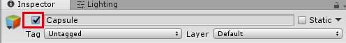
Step3.Setting object-level rendering states
Each object may have its own rendering options. We must install these options into the rendering context before rendering any primitives associated with the object. The most basic property associated with an object is material that describes the surface propertis of the object.
In unity,the material defines how the surface should be rendered,by including referencse to the texutres it uses,tiling information,color tints and so on. The avaliable options for a material depend on which shader the material is using.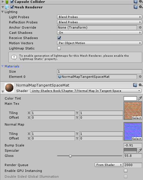
Step4.Geometry generation/delivery
The geometry is actually submitted to the rendering API.Typically,the data is delivered in the form of triangles;either as individual triangles,or an indexed triangle mesh,triangle strip,or some other form.
If you have heard about 3D Max or Maya,then you can get it.The artists create the model in the form of .obj file, we programmers load the model to the RAM, then we got the triangles data. You can achieve the obj_loader.h. Then you can get the triangles data like this:
1 | std::vector<Triangle*> TriangleList; |
In unity, this is done by the powerful engine.
Step5.Vertex-level operations
Once we have the geometry in some triangulated format,a number of various operations are performed at the vertex level. The most important operation is the transformation of vertex positions from modeling space into camera space/clip space.
In unity, this operation is performed by a user-supplied microprogram called vertex shader. Like this:
1 | struct a2v |
Though Unity has encapsulated the transformation function for us,there exists lots things to write. 🌟 We all know that the models that artists give us is in the model space,then how to transform them to the world space/camera space(view space)/clip space/screen space? How to deduce the matrixs(mvp)? What is the coordinates difference among OpenGL,DirectX and Unity? I will describe those in the Appendix :) Actually,the details have confused me for a long time,if you have the same feeling,don’t worry.Just go ahead.
After we transformed the triangles to the camera space, any portion of a triangle outside the view frustum is removed, by the process known as clipping. Here the mvp matrix have ended. Once we have a clipped polygon in 3D clip space, we then project the vertices of that polygon,mapping them to 2D screen-space coordinates of the output window, here the viewport matrix is used.
Step6.Rasterization
Once we have a clipped polygon in screen space,it is rasterized. Rasterization refers to the process of selecting which pixels on the screen should be drawn for a particular triangle; interpolating texture coordinates, colors, and lighting values that were computed at the vetex level across the face for each pixel; and passing these down to the next stage for pixel(fragment) shading. The pseudo-code is as follows:
1 | ...got the TriangleList |
Attention: in the code above, why we need the shadingcoords. That’s because, variable x,y is in the screen space, but the shading process should be done in the world space/view space/clip space.
In unity, rasterization is mostly done by the powerful engine, but we can control the process of viewport to adjust the game to different resolution platforms and control the shader part to get more amazing effects.
Step7.Pixel(fragment) shading
We compute a color for the pixel,a process known as shading. The innocuous phrase “compute a color” is the heart of computer graphics! In unity, we write the fragment shader to compute the pixel colors under different lighting models. code-snippet as follows,from [3].
1 | fixed4 frag(v2f i) : SV_Target |
From the code we can see that the fragment shader computes the ambient,diffuse,specular,the MainTex & BumpMap texture controls the coefficients value of lighting model formulas.
The lighting model is much more than you see. There are many physical formulas. But they are not hard to understand. You can get the details from the reference books[1][2][3].
Step8.Blending and Output
Finally! At the bottom of the render pipeline, we have produced a color,opacity, and depth value. The depth value is tested against the depth buffer for per-pixel visibility determination to ensure that an object farther away from the camera doesn’t obscure one closer to the camera. Pixels with an opacity that is too low are rejected, and the output color is then combined with the previous color in the frame buffer in a process known as alpha blending.
SUMMARY
OK! Now the 8 steps have all been listed. You may want to overview the rough processes. The pseudocode summarizes the simplified rendering pipeline outlined above, from[1].
1 | // First , figure how to view the scene |
Appendix
Since we referred to Coordinates Transformation in Step5. I guess you may not very clear about the internal matrixs and the workflow. Come on baby! Time to overcome the difficulties!![Fig1. coordinate convertion (from [1])](/images/Rendering/coordinate-convertion.png)
Model,World,Camera Space,Clip Space
The geometry of an object is initially described in object space,which is a coordinate space local to the object. The information described usually consisits of vertex positions and surface normals.
Object space = Model space = Local space
Form the model space,the vertices are transformed into world space. The transformation from modeling space to world space is often called model transform. Typically,lighting for the scene is specified in world space,but it doesn’t matter what coordinate space is used to perform the lighting calculations provided that the geometry and the lights can be expressed in the same space. So it is not weird that you see lighting calculations in the world space,or view space,or tangent space,or clip space in unity shader file.
From world space,vertices are transformed into camera sapce. Camera space is a 3D coordinate space in which the origin is at the center of projection,one is axis parallel to the direction the camera is facing(perpendicullar to the projection plane),one axis is the intersection of the top and bottom clip planes,and the other axis is the intersection of the left and right clip planes.
Camera space = View space = Eye space
Here we should be alert to the difference between left-handed world and right-handed world,as shown in Fig2.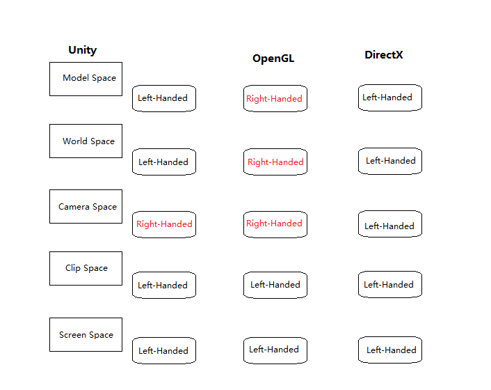
In the left-handed world,the most common convention is to point +z in the direction that the camera is facing,with +x and +y pointing “right” and “up”.This is fairly intuitive,as shown in Fig3.The typical right-handed convention is to have -z point in the direction that the camera is facing.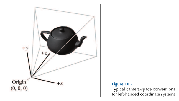
From camera space,vertices are transformed once again into clip space. The matrix that transforms vertices from camera space into clip space is called the clip matrix.
clip space = canonical view volume space
clip matrix = projection matrix
👉More Learning on Transformation and Matrix >>
References:
[1]3D Math Primer for Graphics and Game Development 2nd Edition.
[2]Fundamentals of Computer Graphics and 3rd Edition.
[3]Unity+Shader入门精要
[4]Unity3d Mannual
[5]GAMES