Keywords: Surface Shading, Texture mapping
How to Understand Shading?
How to understand shading? Just like everything does in the real world, all the scenes we see are under different ligths : the sun, the lamp, the flash light etc. Shading is kind of a technique that has a significant relationship with lights and will present the colorful drawings to us at last. Surface shading means the surface is ‘painted’ with lights, it’s a process of applying a material to an object.
The Standard Local Lighting Model
I bet that you have heard the term: BRDF(Bidirectional Reflectance Distribution Function) which seems to have inextricable linkes to the Standard Lighting Model. Yes,BRDF will appear in PBS(Physically Based Shading) which is used to make more realistic modeling presenting the reactions between lights and materials. As for Standard Local Lighting Model, they can be considered as simplified versions of PBS, they are empirical models, but they are easier to understand.
The Standard Lighting Equation Overview
The Standard Lighting Model only cares about direct light (direct reflection).Lights are special entities without any corresponding geometry,and are simulated as if the light were emitting from a sight point. The rendering equation is an equation for the radiance outgoing from a point in any particular direction,the only outgoing direction that mattered in those days were the directions that pointed to the eye. Why say that? Because you know the real world doesn’t work like this where the light may reflect for dozens of times and the process is really complicated, the cost is also a luxury that could not yet be afforded.
The basic idea is to classify coming into the eye into four distinct categories, each of which has a unique method for calculating its contribution. The four categories are :
Emissive contribution,denoted as $c_{emis}$. It tells the amount of radiance emitted directly from the surface in the given direction. Note that without global illumination techniques,these surfaces do not actually light up anything(except themselves).
Specular contribution,denoted as $c_{spc}$. It accounts for light incident directly from the light source that is scattered preferentially in the direction of a perfect “mirror bounce”.
Diffuse contribution,denoted as $c_{diff}$. It accounts for light incident directly from the light source that is scattered in every direction evenly.
Ambient contribution,denoted as $c_{amb}$. It is a fudge factor to account for all indirect light.
![Fig1. lighting-component-overview(from[5])](/images/Rendering/lighting-component-overview.png)
The Ambient and Emmisive Components
To model light that is reflected more than one time before it enters the eye,we can use a very crude approximation known as “ambient light”. The ambient portion of the lighting equation depends only on the properties of materials and an ambient lighting value,which is often a global value used for the entire scene.
$$
c_{amb} = g_{amb} \cdot m_{amb}
\tag{1}
$$
The factor $m_{amb}$ is the material’s “ambient color”. This is almost always the same as the diffuse color (which is often defined using texture map). The other factor,$g_{amb}$,is the ambient light value.
Somtimes a ray of light travels directly from the light source to the eye,without striking any surface in between. The standard lighting equation accounts for such rays by assigning a material an emissive color. For example,when we render the surface of the light bulb,this surface will probably appear very bright,even if there’s no other light in the scene,because the light bulb is emitting light.
In many situations,the emissive contribution doesn’t depend on environmental factor; it is simply the emissive color of the material.
$$
c_{emis} = m_{emis}
\tag{2}
$$
The Diffuse Component
For diffuse lighting, the location of the viewer is not relevant,since the reflections are scattered randomly, and no matter where we position the camera,it is equally likely that a ray will be sent our way.
![Fig2. diffuse-component(From[1]))](/images/Rendering/diffuse-component.png)
But the direction if incidence l,which is dictated by the position of the light source relative to the surface, is important. Diffuse lighting obeys Lambert’s law: the intensity of the reflected light is proportional to the cosine of the angle between the surface normal and the rays of light.
![Fig3. lambert-law(from[5])](/images/Rendering/lambert-law.png)
We calculate the diffuse component according to Lambert’s Law:
$$
c_{diff} = c_{light} \cdot m_{diff} \cdot max(0,n \cdot l)
\tag{3}
$$
as before, n is the surface normal and l is a unit vector that points towards the light source. The factor $m_{diff}$ is the material’s diffuse color, which is the value that most people think of when they think of the “color” of an object. The diffuse material color often comes from a texture map. The diffuse color of the light source is $c_{light}$.
On thing needs attention, that is the max(), because we need to prevent the dot result of normal and light negative, we use $max(0,n \cdot l)$, so the object won’t be lighted by the rays from it’s back.
The Specular Component
The specular component is what gives surfaces a “shiny” appearance. If you don’t understand what a specular is, think about the professional term in animes:
Now let’s see how the standard model calculates the specular contribution. For convenience,we assume that all of these vectors are unit vectors.![Fig5. specular-component(from[1]))](/images/Rendering/specular-component.png)
n is the local outward-pointing surface normal
v points towards the viewer.
l points towards the light source.
r is the reflection vector, which is the direction of a “perfect mirror bounce.” It’s the result of reflecting l about n.
$\theta$ is the angle between r and v.
Of the four vectors, you can see the reflection vector can be computed by
![Fig6. reflection-vector(from[1]))](/images/Rendering/reflection-vector.png)
The Phong Model for specular reflection is :
$$
c_{spec} = c_{light} \cdot m_{spec} \cdot max(0,v \cdot r)^{m_{gls}}
\tag{4}
$$
$$
r = 2(n \cdot l)n-l
$$
$m_{gls}$ means the glossiness of the material,also known as the Phong exponent, specular exponent, or just as the material shininess. This controls how wide the “hotspot” is - a smaller $m_{gls}$ produces a larger, more gradual falloff from the hotspot,and a larger $m_{gls}$ produces a tight hotspot with sharp falloff. $m_{spec}$ is related to “shininess”, it represents the material’s specular color. While $m_{gls}$ controls the size of the hotspot, $m_{spec}$ controls its intensity and color. $c_{light}$ is essentially the “color” of the light, which contains both its color and intensity.
But!!We usually use Blinn Phong Model instead of Phong Model.
![Fig7. blinn-phong-model(from[1])](/images/Rendering/blinn-phong-model.png)
The Blinn phong model can be faster to implement in hardware than the Phong model, if the viewer and light source are far enough away from the object to be considered a constant,since then h is a constant and only needs to be computed once. But when v or l may not be considered constant, the Phong model calculation might be faster.
The Blinn Phong Model for specualr reflection is :
$$
c_{spec} = c_{light} \cdot m_{spec} \cdot max(0,n \cdot h)^{m_{gls}}
\tag{4}
$$
$$
h = \frac{v + l}{|v + l|}
$$
In real coding, vector in the above (1)(2)(3)(4) should be unit vector
Limitations of the Standard Model
Why learn about this ancient history? First, it isn’t exactly ancient history, it’s alive and well. Second,the current local lighting model is one that content creators can understand and use. A final reason to learn the standard lighting model is because
many newer models bear similarities to the standard model, and you cannot
know when to use more advanced lighting models without understanding
the old standard.
![Fig8. all-lighting-equation(from[1])](/images/Rendering/all-lighting-equation.png)
Since Blinn Phong Model contains all the components above,so we call the it Blinn-Phong. Actually, there are several important physical phenomena not properly captured by the Blinn-Phong model. Such as Fresnel reflectance. (:) We’ll discuss this PBS part in the Appendix).
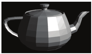
Flat & Gouraud Shading
This part is about the Shading Frequencies. Are you confused? If not, it’s impossible. Because I’m confused at the first time learning and the second time learning. But now, I got it. So come with me.
On modern shader-based hardware, lighting calculations are usually done on a per-pixel basis. By this we mean that for each pixel, we determine a surface normal (whether by interpolating the vertex normal across the face or by fetching it from a bump map), and then we perform the full lighting equation using this surface normal. This is per-pixel lighting, and the technique of interpolating vertex normals across the face is sometimes called Phong shading, not to be confused with the Phong calculation for specular reflection. The alternative to Phong shading is to perform the lighting equation less frequently (per face, or per vertex). These two techniques are known as flat shading and Gouraud shading, respectively. Flat shading is almost never used in practice except in software rendering. This is because most modern methods of sending geometry efficiently to the hardware do not provide any face-level data whatsoever. Gouraud shading, in contrast, still has some limited use on some platforms. Some important general principles can be gleaned from studying these methods, so let’s examine their results.
Phong shading ≠ Phong Reflection Model ≠ Blinn Phong Reflection Model
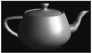
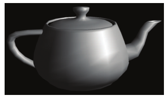
![Fig9. shading-frequency(from[5])](/images/Rendering/shading-frequency.png)
The table below can list differences among them.
| per-pixel lighting | per-vertex lighting | per-face lighting |
|---|---|---|
| Phong shading | Gouraud shading | Flat shading |
| Interpolate normal vectors across each triangle | Interpolate colors from vertices across triangle | Triangle face is flat — one normal vector |
| Compute full shading model at each pixel | Each vertex has a normal vector | Not good for smooth surfaces |
 |
# | |
 |
 |
 |
Mostly used is phong shading
Talk is cheap, show me the code. Here’s a code (from[3])
1 | //per-pixel lighting |
The result is :
![Fig9. phong-shading(from[5])](/images/Rendering/phong-shading.png)
Light Sources
If you have used Unity, you won’t forget different kinds of lights.
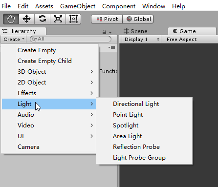
Standard Abstract Light Types
- A point light source represents light that emanates from a single point outward in all directions. Point lights are also called omni lights (short for “omnidirectional”) or spherical lights.A point light has a position and color, which controls not only the hue of the light, but also its intensity. Point lights can be used to represent many common light sources, such as light bulbs, lamps, fires, and so forth.
point light = omni light = spherical light
![Fig10. spot-light(from[1])](/images/Rendering/spot-light.png)
- A spot light is used to represent light from a specific location in a specific direction. These are used for lights such as flashlights, headlights, and of course, spot lights~ As for A conical spot light, it has a circular “bottom”, the width of the cone is defined by a falloff angle(not to be confused with the falloff distance). Also, there is an inner angle that measures the size of the hotspot.
![Fig11. conical-spot-light(from[1])](/images/conical-spot-light.png)
- A directional light represents light emanating from a point in space sufficiently far away that all the rays of light involved in lighting the scene (or at least the object we are currently considering) can be considered as parallel. Directional lights usually do not have a position, at least as far as lighting calculations are concerned, and they usually do not attenuate. Like the sun and moon in our real world.
Directional light = parallel light = distant light
![Fig12. directional-light(from[4])](/images/directional-light.png)
- An area light is only useful in bake. So we don’t talke about it here.
Here’s intuitional effects among the lights.
![Fig13. light-effects(from[4])](/images/light-effects.png)
Light Attenuation
In the real world, the intensity of a light is inversely proportional to the square of the distance between the light and the object, as
$$
\frac{i_1}{i_2} = (\frac{d_2}{d_1})^2
\tag{1}
$$
where i is the radiant flux (the radiant power per unit area) and d is the distance. This part will be mentioned again in the RayTracing article, it’s about Radiometry. Here you just need to know that the final amount of emitted light is obtained by multiplying the light color by its intensity:
light amount = light color * light intensity
![Fig14. light-falloff(from[5])](/images/light-falloff.png)
Actually,I haven’t used light-falloff in my coding. Also this blog is for the novices, so let’s continue with a simple practice and finish this part. Just rememeber that this is the very primary part.
Talk is cheap, show me the code.(frome[3])
1 | Shader "Unity Shaders Book/Chapter 9/Forward Rendering" { |
If you want to know the rendering order,you can use the Frame Debug, this tool is really useful. I think as the study goes further, this part will be mentioned again. Also this is my learning curve, maybe it matches you too. So go on with my articles.
Texture Mapping
Finally, here comes the texture mapping!I am already gearing up and eager to try. Cuz I really want to overview the shadow mapping and opacity blend again. And there are too many things cannot learn forward without the knowledge of texture.
What is a Texture?
There is much more to the appearance of an object than its shape. Different objects are different colors and have different patterns on their surface. One simple yet powerful way to capture these qualities is through texture mapping. A texture map is a bitmap image that is “pasted” to the surface of an object.
![Fig15. texture(from[5])](/images/texture.png)
bitmap image is pixel-image, on the contrary, vector-image
So a texture map is just a regular bitmap that is applied onto the surface of a model. Exactly how does this work? The key idea is that, at each point on the surface of the mesh, we can obtain texture-mapping coordinates, which define the 2D location in the texture map that corresponds to this 3D location. Traditionally, these coordinates are assigned the variables (u,v), where u is the horizontal coordinate and v is the vertical coordinate; thus texture-mapping coordinates are often called UV coordinates or simply UVs.
On thing needs attention : The origin is in the upper left-hand corner of the image, which is the DirectX-style convention, or in the lower left-hand corner, the OpenGL conventions.In unity, the powerful engine has solved the problem for us, unity use uniform left-hand corner as OpenGL.
![Fig16. uv-coordinates-in-unity(from[3])](/images/uv-coordinates-in-unity.png)
Although bitmaps come in different sizes, UV coordinates are normalized such that the mapping space ranges from 0 to 1 over the entire width(u) or height (v) of the image, rather than depending on the image dimensions. We typically compute or assign UV coordinates only at the vertex level, and the UV coordinates at an arbitratry interior position on a face are obtained through interpolation (:) See in Appendix)
So the pseudo-code of UV mapping should be:
1 | //c++ |
Texture Magnification
UV coordinates outside of the range [0,1] are allowed, and in fact are quite useful. Such coordinates are interpreted in a variety of ways. The most common addressing modes (Wrap Mode) are repeat (also known as tile or wrap) and clamp.
When repeating is used, the integer portion is discarded and only the fractional portion is used, causing the texture to repeat. Under clamping, when a coordinate outside the range [0,1] is used to access a bitmap, it is clamped in range. This has the effect of streaking the edge pixels of the bitmap outwards. The mesh in both cases is identical: a single polygon with four vertices. And the meshes have identical UV coordinates. The only difference is how coordinates outside the [0,1] range are interpreted. See Fig17.
![Fig17. uv-warp-mode(from[1])](/images/uv-warp-mode.png)
If you have used Unity, this is not strange to you. See the example below(from[3]).
![Fig17-1. wrap-mode-repeat(from[3])](/images/wrap-mode-example.png)
![Fig17-2. wrap-mode-clamp(from[3])](/images/wrap-mode-example-1.png)
The shader code on the materail of the Quad is :
1 | Shader "Unity Shaders Book/Chapter 7/Texture Properties" { |
I think you have noticed the code //o.uv = v.texcoord.xy * _MainTex_ST.xy + _MainTex_ST.zw; Look at the gif below, _MainTex_ST.xy means Tiling, _MainTex_ST.zw means offset.

Also, I think you have noticed that there is Mipmap & FilterMode properties in the panel of Fig17-1, what’s the meaning of these? You see that in Unity, the png is 512*512, it matches the Quad just in time. What if the texture(png) is too small? It’s easy to imagine, that you have an image, but the object is too giant, you need some methods to let the texture ‘pasted’ on the object surface without low resolution/distortion.
![Fig19. filter-mode(from[5])](/images/filter-mode.png)
Here I want to infer Bilinear Interpolation (:) see it in the Appendix)
Then What if the texture(png) is too large? Here comes Mipmap (This part is a little hard for me. so Jump over it and later back..)
Different Types Texture Mapping
There are too many types of texture mapping.
Bump Mapping
Bump mapping is a general term that can refer to at least two different methods of controlling the surface normal per texel.
A height map is a grayscale map, in which the intensity indicates the local “elevation” of the surface. Lighter colors indicate portions of the surface that are “bumped out,” and darker colors are areas where the surface is “bumped in.” Height maps are attractive because they are very easy to author, but they are not ideal for real-time purposes because the normal is not directly available; instead, it must be calculated from the intensity gradient. (We wil talk about it in Displacement Mapping)
A bump map, which is very common nowadays, is Normal Mapping.
![Fig20. two-bumping-methods(from[5])](/images/two-bumping-methods.png)
Normal Mapping
In a normal map, the coordinates of the surface normal are directly encoded in the map. How could a bump map save the surface normal of the object? Of course, the color. The most basic way is to encode x, y, and z in the red, green, and blue channels. Since the normal vector is bounded in [-1,1],and the color channel component is bounded in [0,1], so there should be a principle:
$$
pixel = \frac{normal + 1}{2}
$$
Seems easy~ The bump map storse the normal vectors in model space in terms of pixels(rgb). Voila! If only it were that easy.
Real-world objects exhibit a great deal of symmetry and self-similarity, and patterns are often repeated. For example, a box often has similar bumps and notches on more than one side. Because of this, it is currently a more efficient use of the same amount of memory (and artist time) to increase the resolution of the map and reuse the same normal map (or perhaps just portions of it) on multiple models (or perhaps just on multiple places in the same model). Of course, the same principle applies to any sort of texture map, not just normal maps. But normal maps are different in that they cannot be arbitrarily rotated or mirrored because they encode a vector. Imagine using the same normal map on all six sides of a cube. While shading a point on the surface of the cube, we will fetch a texel from the map and decode it into a 3D vector. A particular normal map texel on the top will produce a surface normal that points in the same direction as that same texel on the bottom of the cube, when they should be opposites! We need some other kind of information to tell us how to interpret the normal we get from the texture, and this extra bit of information is stored in the basis vectors.
So there comes the Tangent Space.
In tangent space, +z points out from the surface; the +z basis vector is actually just the surface normal n. The x basis vector is known as the tangent vector, which we’ll denote t, and it points in the direction of increasing t in texture space. Similarly, the y basis vector, known as the binormal and denoted here as b, corresponds to the direction of increasing b, although whether this motion is “up” or “down” in the texture space depends on the conventions for the origin in (t,b) space, which can differ, as we discussed earlier. The coordinates for the tangent and binormal are given in model space.
![Fig21. tangent-space(from[3])](/images/tangent-space.png)
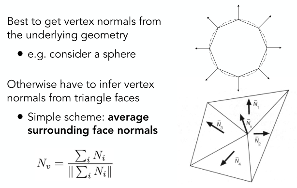
And how to calculate basis vectors as the average of adjacent triangle normals?Here’s the formula & code(from[1])
We are given a triangle with vertex positions $p_0 = (x_0 ,y_0 ,z_0 ), p_1 = (x_1 ,y_1 ,z_1 ), and p_2 = (x_2 ,y_2 ,z_2),$ and at those vertices we have the UV coordinates $(u_0 ,v_0 ), (u_1 ,v_1 ), and (u_2 ,v_2 ).$
$$
q_1 = p_1 − p_0 , s_1 = u_1 − u_0 , t_1 = v_1 − v_0
$$
$$
q_2 = p 2 − p_0 , s_2 = u_2 − u_0 , t_2 = v_2 − v_0.
$$
$$
tangent = t_2q_1 - t_1q_2 , binormal = -s_2q_1 + s_1q_2
$$
1 | //c++ |
In unity, you can calculate the lighting model in the world space with bump textures.Here an example.(from[3])
1 | Shader "Unity Shaders Book/Chapter 7/Normal Map In World Space" { |
![Fig22. unity-normal-map(from[3])](/images/unity-normal-map.png)
Displacement Mapping
A height map (or true displacement map) can be easily painted in Photoshop; Since normal map is clear , displacement is not hard for you.
A displacement map actually changes the geometry using a texture. A common simplification is that the displacement will be in the direction of the surface normal.
![Fig23. displacement-map(from[2])](/images/displacement-map.png)
$$
p\prime = p + f(p)n.
$$
Environment Mapping
Often we want to have a texture-mapped background and for objects to have specular reflections of that background. This can be accomplished using environment maps; There are many ways to store environment maps. Here is the most common method cube map.
If you have used Unity, then you’ll be familiar with cube map, yes, the sky box~ In ideal cases, we want to generate the corresponding cube map for the objects of different positions in the scene. So the smart way is to write scripts. Here’s an example
1 | using UnityEngine; |
Shadow Maps
Here comes the shadow map.
Opacity Blending
Appendix:
PBS
This part will be explained in First-Met-With-RayTracing.
Interpolation
Before learning CG, I couldn’t understand the term interpolation. Now it’s time write something about it.
There are many interpolation methods, today I want to introduce a common method, called Barycentric Coordinates - used in Interpolation Across Triangles. If you have read the above the paragraphs carefully, you can see the barycentric coordinates method has appeared before.
Why do we want interplate?
Specify values at vertices
Obtain smoothly varying values across triangles
What do we want to interpolate?
- Texture coordinates, colors, normal vectors, …
Barycentric Coordinates: Formulas
![Fig15. Barycentric-Coordinates(from[5])](/images/Barycentric-Coordinates.png)
$$
\alpha = \frac{-(x-x_B)(y_C - y_B) + (y-y_B)(x_C-x_B)}{-(x_A-x_B)(y_C-y_B) + (y_A-y_B)(x_C-x_B)}
\tag{Barycentric Coordinates: Formulas}
$$
$$
\beta = \frac{-(x-x_C)(y_A-y_C) + (y-y_C)(x_A-x_C)}{-(x_B-x_C)(y_A-y_C) + (y_B-y_C)(x_A-x_C)}
$$
$$
\gamma = 1 - \alpha - \beta
$$
Using Barycentric Coordinates
![Fig15. using-barycentrics(from[5])](/images/using-barycentric.png)
talk is cheap, show me the code
1 | //c++ |
Bilinear Interpolation
Since we mentioned bilinear interpolation in the texture magnificient part. So let’s go straight.
![bilinear-interpolation(from[5])](/images/bilinear-interpolation.png)
- Step1. We want to sample texture f(x,y) at red point, black points indicate texture sample locations.
- Step2. Take 4 nearest sample locations, with texture values as labeled.
- Step3. Calculate fractional offsets,(s,t)
- Step4.
$$
lerp(x,v_0,v_1) = v_0 + x(v_1 - v_0)
\tag{Linear interpolation (1D)}
$$
$$
u_0 = lerp(s,u_{00},u_{10})
$$
$$
u_1 = lerp(s,u_{01},u_{11})
\tag{Two helper lerps}
$$
$$
f(x,y) = lerp(t,u_0,u_1)
\tag{Final vertical lerp, to get result}
$$
talk is cheap, show me the code
1 | //c++/opencv |
For the code above, I have a few words to add:
In opencv:
Mat image;
image.at<>(i,j) i–>y j–>x
color order : BGR
the origin is at the upper-left corner
Another one, Since have learned that one pixel can be seen as a little square. and the center of the pixel is (x + 0.5,y + 0.5); I tried this experiment using OpenCV, and found that : the result shows that they represent the same pixel.
1 | window.at<cv::Vec3b>(1,1)[1] = 255 |
References:
[1]3D Math Primer for Graphics and Game Development 2nd Edition.
[2]Fundamentals of Computer Graphics and 3rd Edition.
[3]Unity+Shader入门精要
[4]Unity3d Mannual
[5]GAMES
[6]scratchapixel